


Digital Interferometry is a new concept for optical interferometry, which combines the high sensitivity of conventional optical interferometry with the robustness of digital modulation/demodulation techniques to achieve a breakthrough combination of sensitivity, ease of use and flexibility.
DI employs a digital pseudo-random noise (PRN) code phase-modulated onto the light source, which allows optical signals to be isolated based on their delay. This signal isolation capability is exploited in a number of ways. First, it improves measurement sensitivity by reducing contamination by spurious interference. Second, it allows multiple optical components to be measured using a single metrology system. Finally, DI allows a dramatic simplification and miniaturization of the optical system. The basic concept [1] and a first experimental verification [2] were published in late 2007. More recently, picometre-level performance was demonstrated for an optical cavity measurement [3].
Interferometric signals on a single photodetector are effectively time-tagged by phase modulating the laser source with a PRN code. Consider the optical layout shown in Figure 1 for the case of 3 reflectors: A beamsplitter divides the laser output into a local oscillator and probe beam. The local oscillator is frequency-shifted by an acousto-optic modulator (AOM) to provide a heterodyne signal at the photodetector with a frequency fh. A PRN code generator drives an electro-optic modulator (EOM) to produce either a zero or pi phase shift on the probe beam before it is directed towards the mirrors. The reflected light is recombined with the local oscillator and the interference signal is measured by the photodetector.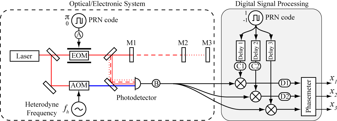
Figure 1: Digital Interferometer for monitoring displacements of three mirrors M1, M2, and M3. Each reflection is isolated by matching the decoding delays to the optical delay. Signals measured at points A, B, C1, C2, D1, and D2 are shown in Figure 2.
The key difference from a conventional heterodyne interferometer is the PRN phase modulation. With no PRN modulation, the heterodyne signal at the photodetector is determined by the vector sum of the reflections from both mirrors. Information about the individual mirror positions is lost. With the PRN modulation present, the signal from each mirror will possesses a time-varying phase shift unique to its time of flight from the EOM.
The effect of the PRN encoding and decoding on the measured signals is shown in Figure 2. For clarity we will consider the encoding and decoding with only the M1 reflection present (e.g. M2, M3 blocked). The first row shows the signal at the photodetector in a conventional heterodyne interferometer. With DI, the PRN code (A) randomly inverts the amplitude of the heterodyne signal at the photodetector producing the chopped sine wave (B). In the processing channel for monitoring M1 (centre column), the photodetector output is multiplied by the PRN code with a matching delay (C1), to recover the full heterodyne signal (D1). The phase of this heterodyne signal gives the mirror displacement x1. The M2 channel (right column) uses a different decoding delay (C2); in this case the signal is randomly re-inverted (D2) and appears as a broadband noise background to the measurement. This broadband noise can be strongly rejected by appropriate filtering and averaging in the phasemeter. This demonstrates that by adjusting the decoding delay, we can selectively isolate signals based on their total optical/electronic delay, referred to here as ‘range-gating’.
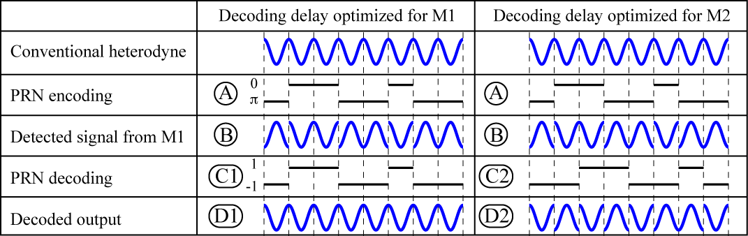
Illustration of signals from one mirror (M1) with matched (centre column) and unmatched (right column) decoding delays. Signals A, B, C1, C2, D1, D2 correspond to the measurement points in Figure 1. The decoded output is subsequently bandpass filtered to extract the signals; the near pure tone of the centre column will be passed by the filter giving a clear signal for M1, while the noisy signal in the right column will be blocked by the filter and the M1 signal will not contaminate the M2 output.
References:
[1] Shaddock Opt Lett 2007
[2] Lay et al. Opt Lett 2007
[3] de Vine et al. Opt. Express 2009