Laser beam steering subsystem - an optical phased array
For Laser beam steering subsystem - an optical phased array
Project status
Content navigation
About
Laser beam steering subsystem - an optical phased array
Phased arrays are employed in several types of modern devices, including medical ultrasound emitters and military radar. Their primary purpose is to precisely steer a beam of sound or electromagnetic waves without using any moving parts. The basic principle is to use an array of transmitters and then control the phase of the wave that each transmitter produces. The combined wavefront from all the transmitters can then exhibit certain desired properties, such as travelling in a particular direction or having a certain shape. This is illustrated in Figure 1.
GRACE Follow On Project: Optical-Phased Array explained

Figure 1: Three examples of a phased array emitting a wave. Left: the array is timed such that the combined wavefront travels directly away from the array. Center: the wavefront travels at an angle. Right: the wave front appears to come from a single point source behind the array.
This is relatively straightforward if the wave frequencies are small enough that the signals can be produced by a digital system, which is the case for ultrasound and radar. For visible and near-infrared (i.e., optical) light, however, which have frequencies exceeding 1017 Hz (that’s 100 million GHz), this is not possible.
An alternative option is to generate a highly coherent light wave and split it among multiple paths, each with a variable length. By controlling the length of the different paths we control how long it takes the light to travel through it and thus the phase of the light when it comes out. Fortunately we have the tools to make this happen: lasers are perfect for generating coherent light and optical fibres are waveguides, designed specifically to guide light along a path.
In the simplest scenario, we could simply use an optical fibre array (such as the one in Figure 2) which has many fibres bundled together in a single package. The light from the laser would be divided and sent along different optical paths in the different fibres. Each fibre would have its own electronic ‘stretcher’ (really an electro-optic-modulator) that would change the path length in that fibre. By sending the appropriate signals to each ‘stretcher’, we would then have an optical phased array.
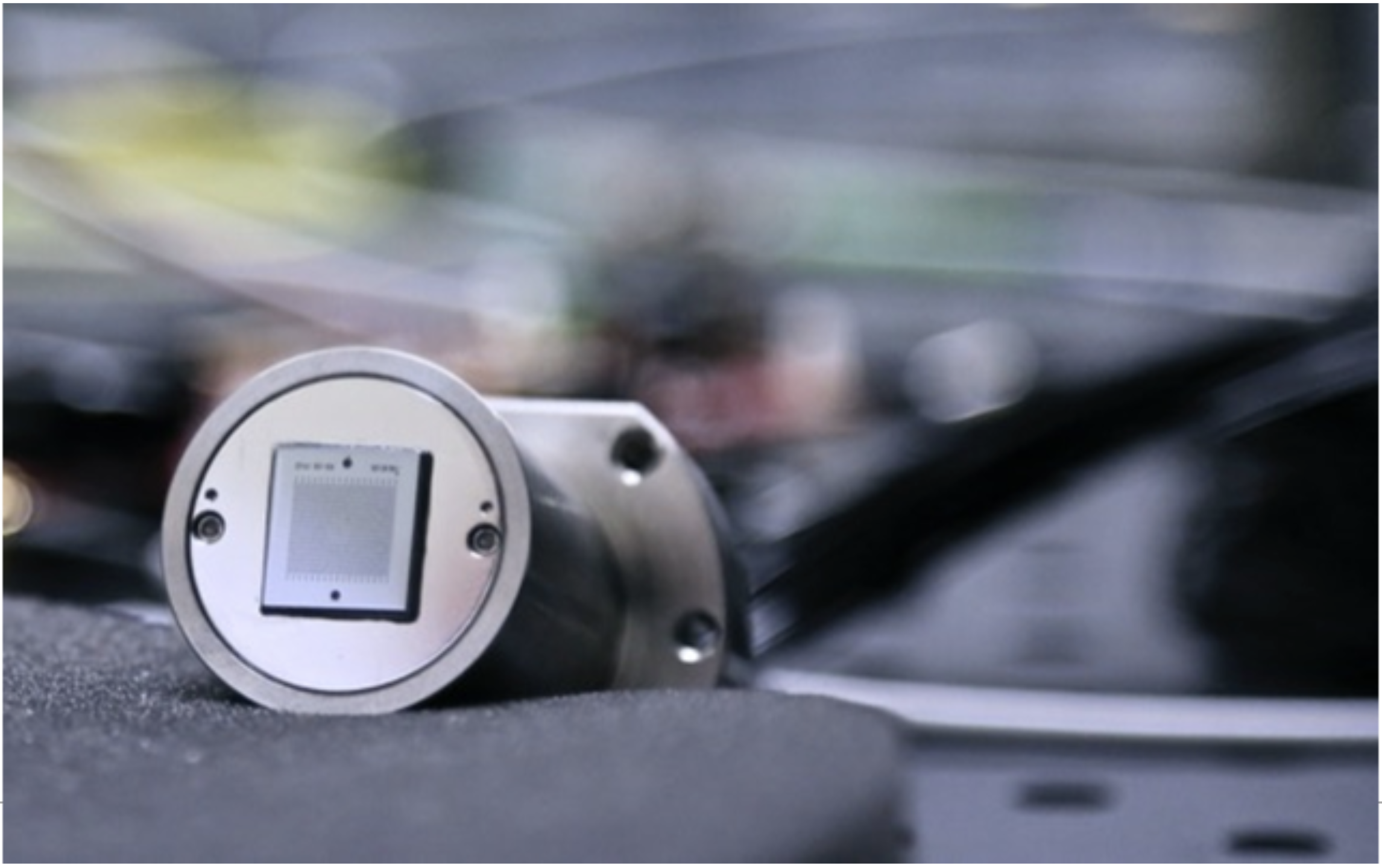
Figure 2: Custom designed optical-fiber array.
Unfortunately a system such as described above would be overwhelmed by noise, and would not function as envisioned. For a phased array to work properly, the relative phases need to be adjusted to within a fraction of a wavelength. With optical wavelengths being typically around 1 micrometre, this is not straightforward, as normal fluctuations in the temperature of the fibres or mechanical vibrations in the fibres will cause path length changes much larger than this. These external forces will destroy the precise phase relationships among the many fibres making up the optical phased array, and so we need to eliminate them. Since it is not generally possible to adequately insulate our array from these forces, we will instead precisely measure the effect of the forces on each fibre, and then use the fibre-stretchers to compensate for that unwanted effect.
Our plan is shown in Figure 3. By fixing a glass screen (a reference flat) in front of the fibres a small amount of light is reflected from each outgoing fibre back into a return fibre. We can then use a powerful technique called heterodyne interferometry to precisely measure the phase of the returning light, which gives us a measurement of the path length of the outgoing fibre. This phase measurement can then be used to adjust the fibre-stretchers until we have exactly the length, and thus the phase, that we want. This solution is complicated by the fact that the return fibre carries reflected light from all the outgoing fibres, and so we need to descramble it in order to determine the lengths of the individual fibres.

Figure 3: The basic schematic of the optical phased arrary. The path length in each fibre must be precisely measured in real time in order to cancel disturbances due to ambient noise. The technique for this measurement is multi-plexed digital interferometry.
The solution is digitally enhanced heterodyne interferometry, developed at ANU. This involves tagging the light traveling with a pseudo-random noise (PRN) code, with each fibre having a different delay. Each fibre uses a different delay so when the light from multiple fibres travels back down the return fibre and hits our sensor we can use the code combined with the unique, known delays to separate the light based on which outgoing fibre it came from. Now we can precisely measure the changes in length of each outgoing fibre and apply the appropriate control signal to each fibre-stretcher to cancel the distortion. Then using the standard phased array techniques, we have a laser beam steering device with no moving parts. This optical phased array might be used to steer the output beam of GRACE type satellite, or, if built with a high-power laser beam, to actually change the path of space debris.
At ANU Centre for Gravitational Astrophysics, we have already demonstrated that this concept can work, using a one-dimensional system (i.e., it can steer the beam left and right but not up or down) with standard laboratory optical prototyping components. We are currently designing a two-dimensional, integrated system that will be precise, compact, and robust.